Overview of LPT
Definition
Link-state pass through (LPT) transparently transmits the local link status to the opposite end so that the opposite end can perform operations accordingly.
Purpose
Ethernet LPT can detect and report a link fault on the Ethernet user side or a fault on an intermediate point-to-point network.
After detecting a fault on the local link, the local user equipment automatically enables a backup link and uses the backup link to communicate with the opposite user equipment. The opposite user equipment, however, cannot obtain information about the local link fault. Therefore, it still uses the original link to communicate with the local user equipment. As a result, services are interrupted.
Benefits
If Ethernet LPT is enabled, the local user equipment can send information about the local link fault to the opposite network edge equipment using Ethernet LPT packets. The opposite network edge equipment disables the UNI-side port so that the opposite user equipment starts to use the backup link. In this manner, services are transmitted over the backup link between the user equipment at both ends.
Basic Principles
This section describes the implementation principle of Ethernet LPT in a scenario with a user side link fault and a scenario with a point-to-point network fault.Figure 7-1 shows the scenario where a user side link fault occurs.
Figure 7-1 Scenario where a user side link fault occurs
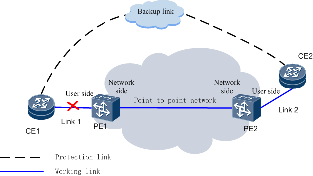
PE1 and PE2 are enabled with Ethernet LPT and transmit packets to each other. When a fault occurs on link 1:
-
CE1 detects that link 1 is malfunctioning and enables the backup link to communicate with CE2.
PE1 periodically transmits Ethernet LPT packets to PE2. After detecting that link 1 is malfunctioning, PE1 sends Ethernet LPT packets containing a message to PE2, indicating that link 1 is malfunctioning.
-
After receiving and interpreting the Ethernet LPT packets, PE2 acknowledges that the user side link of PE1 is malfunctioning and disables its user side port.
After detecting that the user side port of PE2 is disabled, CE2 enables the backup link to communicate with CE1.
After the fault on the user side link of PE1 is rectified, services on the backup link can be switched back to the working link according to the following steps.
-
After detecting that the fault on link 1 is rectified, CE1 switches services on the backup link to the working link and tries to communicate with CE2 using the working link.
After detecting that the fault on link 1 is rectified, PE1 sends Ethernet LPT packets containing a message to PE2, indicating that the fault on its user side link is rectified.
-
After receiving and interpreting the Ethernet LPT packets, PE2 acknowledges that the fault on the user side link of PE1 is rectified and enables its user side port.
After detecting that the user side port is enabled, CE2 switches services on the backup link back to the working link and communicates with CE1 using the working link.
Figure 7-2 shows the scenario where a point-to-point network fault occurs.
Figure 7-2 Scenario where a point-to-point network fault occurs
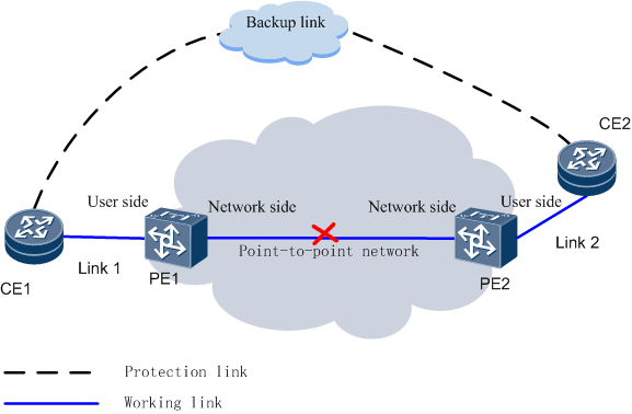
PE1 and PE2 are enabled with Ethernet LPT and transmit packets to each other. When a point-to-point network fault occurs:
-
PE1 receives no Ethernet LPT packets from PE2 and detects that Ethernet LPT communication fails. Then, PE1 disables its user side port.
After detecting that the user side port of PE1 is disabled, CE1 enables the backup link to communicate with CE2.
-
PE2 receives no Ethernet LPT packets from PE1 and detects that Ethernet LPT communication fails. Then, PE2 disables its user side port.
After detecting that the user side port of PE2 is disabled, CE2 enables the backup link to communicate with CE1.
After the point-to-point network fault is rectified, services on the backup link can be switched back to the working link according to the following steps.
-
After receiving and interpreting the Ethernet LPT packets, PE1 detects that the fault is rectified and enables its user side port.
After detecting that the user side port is enabled, CE1 switches services on the backup link back to the working link and tries to communicate with CE2 using the working link.
-
After receiving and interpreting the Ethernet LPT packets, PE2 detects that the fault is rectified and enables its user side port.
After detecting that the user side port is enabled, CE2 switches services on the backup link back to the working link and communicates with CE1 using the working link.